Power Electronics | Wide-Bandgap (SiC/GaN) | CLLC & Dual Active Bridge (DAB) | AI Data Centers | EV Powertrain | Renewable & Grid Integration | Energy Transition | Hyper-Scaling Innovation | Independent Advisor
June 10, 2025
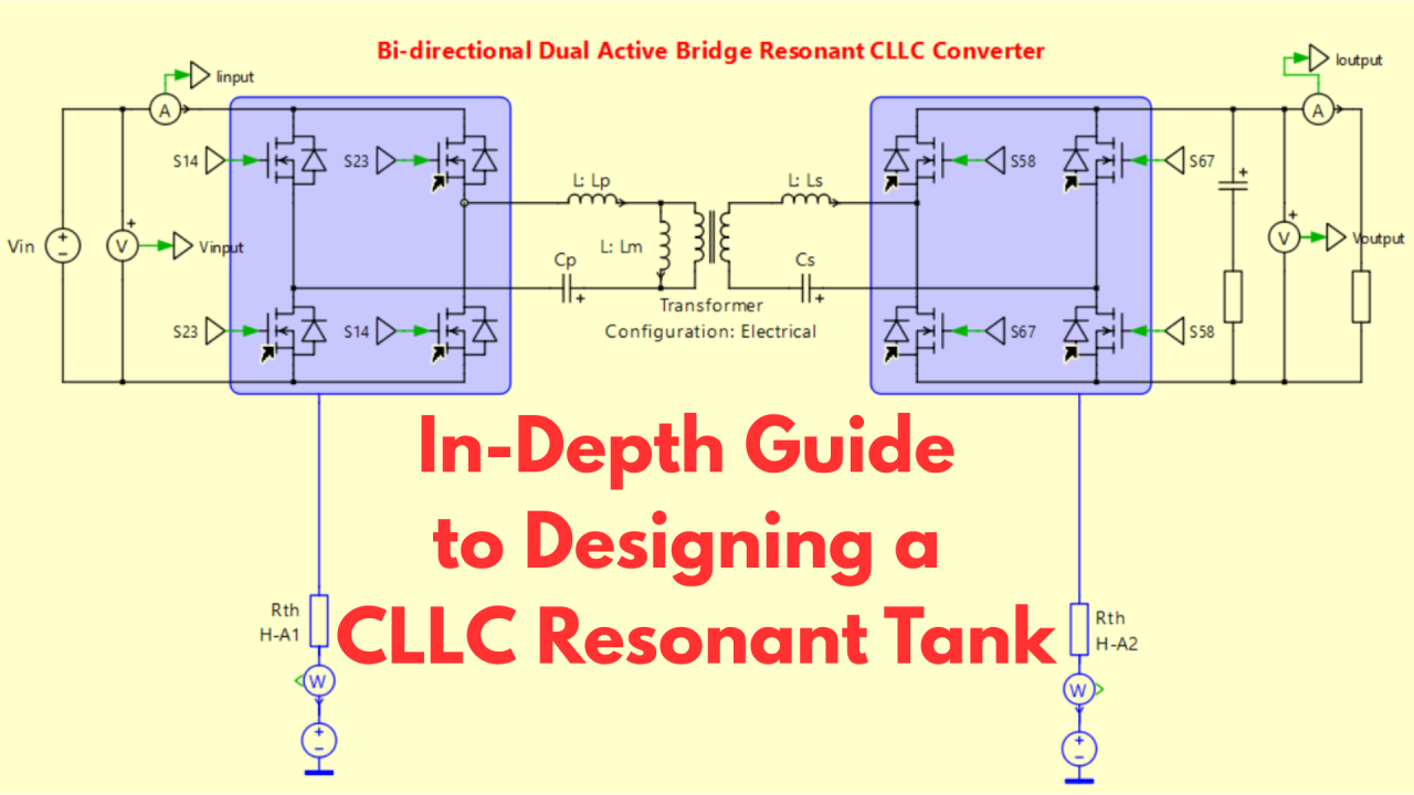
The Bidirectional DAB CLLC resonant converter is a cornerstone in high-efficiency, bidirectional power conversion, particularly for energy storage systems (ESS) and electric vehicle (EV) chargers. Its ability to achieve Zero-Voltage Switching (ZVS) across a wide load range makes it ideal for high-power designs. However, designing the resonant tank comprising Lp, Cp, Lm, Ls, and Cs demands precision to balance efficiency, gain, and operating frequency range.
In this post, I’ll guide you through a detailed design process using mode/state-plane analysis by Mueller [1]. I’ll provide a practical example for a 10 kW DAB CLLC converter, include all relevant formulas and validate the design.
Summary of the Design Process
- Define Operating Parameters: Identify input/output voltages, power, and resonant frequency.
- Determine Gain Requirements: Calculate minimum and maximum normalized gain (M) based on the transformer turns ratio.
- Select Inductance Ratio (Ln): Choose Ln to balance primary current, frequency range, and ZVS.
- Evaluate Normalized Load Power (pon): Use precalculated charts to find the maximum allowable pon.
- Calculate Resonant Tank Parameters: Denormalize to find Lp, Cp, Lm, Ls, and Cs.
- Validate the Design: Check against gain curves, check deadtime requirements, and plan for simulation.
Detailed Design Steps
1. Define Operating Parameters
We start by gathering all operating conditions. For our example:
- Vin_nom = 800 V, Vin_min = 700 V, Vin_max = 900 V (input voltage range).
- Vout = 400 V (output voltage).
- Pout = 10,000 W (output power).
- f_resonance = 500 kHz.
- Topology: Dual Active Bridge with Resonant CLLC.
For a full-bridge topology, the equivalent input voltage (Vin,eq) equals the actual input voltage (Vin). In a half-bridge, it would be Vin/2.
2. Determine Gain Requirements
The normalized gain (M) is defined as:
where n is the transformer turns ratio. At nominal conditions (Vin,nom=800 V, Vout=400 V), we set M=1:
Now, calculate the gain range:
- Minimum gain (Mmin): At Vin,max=900 V:
- Maximum gain (Mmax): At Vin,min=700 V:
The converter must operate between M=0.889 and M=1.143.
3. Select Inductance Ratio (Ln)
The inductance ratio (Ln) is:
where Lp is primary resonant inductance and Lm is the magnetizing inductance.
Since we’re using synchronous rectification (no forced ZCS), we base Ln on the minimum gain:
We select Ln to be 8.00.
4. Evaluate Normalized Load Power (pon)
The normalized load power (pon) represents the resonant tank’s loading. It’s determined using pre-calculated charts reproduced here for clarity from original article [1].