Power Electronics | Wide-Bandgap (SiC/GaN) | CLLC & Dual Active Bridge (DAB) | AI Data Centers | EV Powertrain | Renewable & Grid Integration | Energy Transition | Hyper-Scaling Innovation | Independent Advisor
June 25, 2025
#PowerElectronics #CLLC #DAB #LossAnalysis #HighEfficiency #SiC #GaN #48V #SST #AIInfra #ThermalDesign #ZVS #ZCS #DigitalPower #SolidStateTransformer #800V
As bidirectional DC-DC converters become the backbone of AI data centers, solid-state transformers, and EV power architectures, the Dual Active Bridge (DAB) Resonant CLLC converter stands out for its ability to handle high power with excellent soft-switching.
But to truly optimize it, we need to go beyond schematics and waveforms. We need to ask: Where is the power actually being lost? What are the dominant loss mechanisms in a real-world CLLC converter?
This article breaks down the loss components of DAB Resonant CLLC converters – so we can design smarter, cooler, and more efficient power systems.
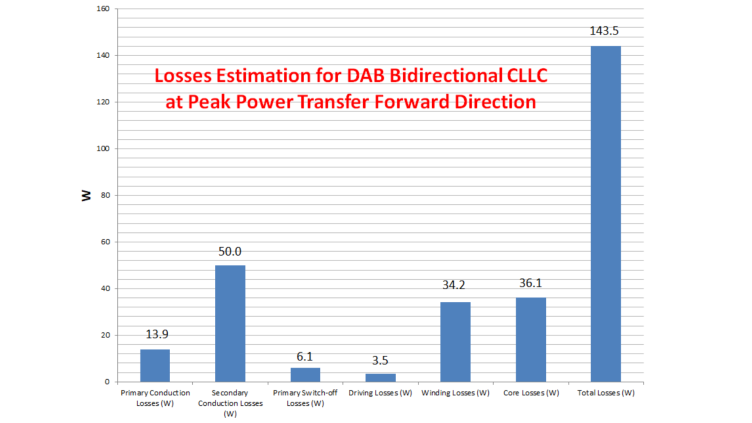
1. Conduction Losses
These arise in:
- Primary and secondary switches (e.g., SiC or GaN FETs)
- Synchronous rectifiers
- PCB copper planes and connector paths
Minimized by:
- Low-Rds(on) devices
- Optimized gate drive and layout
- Proper paralleling of MOSFETs
2. Resonant Tank Losses
The CLLC tank allows soft-switching, but introduces:
- AC conduction losses in transformer
- Proximity losses in Litz wires
- Core losses (frequency-dependent, especially with high-permeability materials)
- ESR losses in resonant capacitors
Minimized by:
- Choosing low-loss magnetic materials
- Ferrites with stable B-H curves at high frequency
- Film capacitors with low ESR or ceramic capacitors (C0G) wherever feasible
3. Switching Losses
Unlike hard-switched DAB, the CLLC reduces turn-on and turn-off losses via:
- ZVS (zero voltage switching) for turn-on for both HV and LV switches
- ZCS (zero current switching) for turn-off for LV switches
- Low turn-off for HV switches
Still, parasitic capacitance and imperfect transitions at light load can contribute.
Minimized by:
- Proper dead time tuning
- Gate drive shaping
- Avoiding frequency too far from resonance
4. Magnetizing Current Losses
The magnetizing branch ensures bidirectional power flow and ZVS. But excessive circulating magnetizing current leads to copper loss + transformer heating.
Trade-off: More magnetizing inductance improves ZVS but increases core and copper losses.
5. Transformer Losses
A high-frequency transformer in the CLLC stage introduces:
- Conduction losses
- Proximity losses in Litz wires
- Core losses
Optimized via:
- Core material selection
- Litz wire
6. Control and Gate Driver Losses
- Gate drive power consumption
- DSP/FPGA power
Why It Matters
Understanding these losses isn’t just academic – it directly impacts:
- Efficiency (every % counts in 10+ kW systems)
- Thermal design (size, cooling, reliability)
- Power density (critical in AI rack or SST modular systems)
- TCO and lifecycle cost
Final Takeaway
The DAB Resonant CLLC converter is a soft-switching powerhouse, but it’s not lossless.
The best designs don’t just work – they balance every loss component carefully.
If you’re building AI rack converters, modular SST cores, or EV bidirectional interfaces, and want to extract maximum performance from your CLLC stage – loss modeling should be your first checkpoint.